

Detailed explanation of the new dimming scheme based on LT3743 LED driver
2021-05-23
In many lighting applications, power drivers that generate modulated current pulses, from high-current LEDs in DLP projectors to high-power laser diodes, etc., are used. For example, in high-end video projectors, high-power LEDs are used to produce colored illumination. The RGB LEDs in these projectors require precise dimming control for accurate color mixing—in this case, in addition to simple PWM dimming, more control is available. In general, to achieve the wide dynamic range required for color mixing, the LED driver must be able to quickly switch between two completely different modulated peak current states and superimpose PWM dimming without any damage. The LT3743 meets these demanding accuracy and speed requirements.
The LT3743 is a synchronous step-down DC/DC controller that uses fixed frequency, average current mode control to accurately regulate inductor current through a sense resistor in series with the inductor. The LT3743 is capable of regulating the current in any load with an accuracy of ±6% over an output voltage range of 0V to "2V below the input rail."
This article refers to the address: http://
Accurate, wide-range LED current control is achieved by combining accurate analog dimming (high-luminosity and low-luminance states) with PWM dimming. Analog dimming is controlled by the CTRL_L, CTRL_H, and CTRL_T pins; PWM dimming is controlled by the PWM and CTRL_SEL pins. By using a unique approach to externally switching capacitors, the LT3743 enables fast transitions between high and low analog states to change the regulated LED current level in a few μs. The switching frequency can be set from 200kHz to 1MHz (by using an external resistor) and synchronized to an external clock with a frequency range of 300kHz to 1MHz.
Switching output capacitor topology
In a conventional current regulator, the voltage across the load is stored in an output capacitor. If the load current changes abruptly, the voltage in the output capacitor must be charged or discharged to match the new regulated current. During the conversion, the current in the load is not well controlled, resulting in a slow load current response time.
The LT3743 solves this problem by using a unique switched-output capacitor topology that achieves ultra-fast load current rise and fall times. The basic concept behind this topology is that the LT3743 acts as a regulated current source that is responsible for supplying the drive current to the load. For a given current, the voltage drop across the load is stored in the first switched output capacitor. When a different regulated current state is required, the first output capacitor is turned off and the second capacitor is turned on. This enables each capacitor to store a load voltage drop corresponding to the desired regulated current.
Figure 1 shows the basic topology with various control pins. The PWM and CTRL_SEL pins are digital control pins that determine the state of the regulated current. The CTRL_H and CTRL_L pins are analog inputs with a full scale range of 0V to 1.5V, producing a regulated voltage of 0mV to 50mV across the current sense resistor.
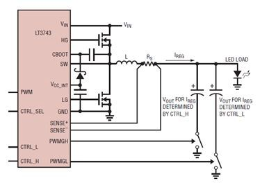
Figure 1: Basic Switched Capacitor Topology
Figure 2 shows the timing waveforms for the various states of the PWM and CTRL_SEL pins. When PWM is low, all switching operations are terminated and both output capacitors are disconnected from the load.
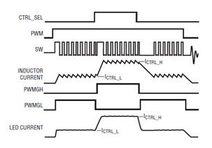
Figure 2: LED Current PWM and CTRL_SEL Dimming
Although the LT3743 can be configured with a switched output capacitor, it can easily accommodate any traditional analog and/or PWM dimming scheme.
Switch cycle synchronization
The LT3743 synchronizes all switching pulse edges to the PWM and CTRL_SEL rising edges. Synchronization gives the system designer the freedom to use any cycle or non-periodic PWM dimming pulse width and duty cycle. For high current LED drivers, this is an essential feature in the recovery from a zero current or low current state to a high current state. By restarting the clock when CTRL_SEL or the PWM signal goes high, the inductor current will immediately begin to ramp up without waiting for a rising edge of the clock. When synchronization is not used, the phase relationship between the clock edge and the PWM pulse edge will be uncontrolled, which may cause significant jitter in the LED light output. When using an external clock with a SYNC pin, the switching cycle is resynchronized to the external clock within 8 switching cycles.
A 24V, 20A LED driver for high-end DLP projectors with switched output capacitors. High-end DLP projectors require extremely high quality images and color reproduction. In order to achieve high color accuracy, the color deviation in each LED is corrected by mixing the colors of the Other two colored LEDs. For example, when the red LED is in full current conduction, the blue and green LEDs will be turned on at a low current level so that they can be mixed in to produce accurate red light. This approach requires the ability to quickly switch between lower (about 2A) and higher (about 20A) LED currents to maintain the PWM dimming edge. Figure 3 shows a 24V/20A LED driver for high-end DLP projectors.
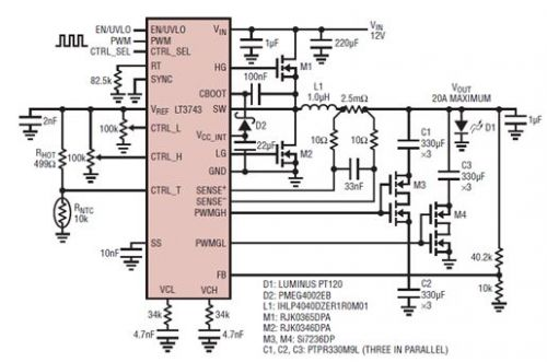
Figure 3: 24V/20A LED Driver with Switched Output Capacitor
The lower switching frequency of 450kHz allows the use of a very small 1.0μH inductor. At 25% ripple current, the transition time between the high current state and the low current state is approximately 2 μs. The large 1mF output capacitor stores the voltage drop across the LED in two different current states and provides the instantaneous current when the MOSFET dimmer switch is turned on. For fast LED current conversion, it is critical to use several low-ESR capacitors in parallel.
The regulated current and low current are set by a voltage divider connected between the VREF pin and the CTRL_L and CTRL_H pins. The ±2%, 2V reference on the VREF pin is also used to provide the reference signal that the temperature derating circuit applies to the CTRL_T pin (see “Thermal Derating of LED Current” below).
To reduce the potentially large startup current, the LT3473 uses a unique soft-start circuit that suppresses the regulated current to provide full drive when the soft-start pin is charged to 1.5V. To minimize the transition time between different current levels, the LT3743 uses separate compensation for each current level so that the current control loop can return to steady state operation as quickly as possible. Figure 4 shows the LED current step from 0A to 2A to 20A.
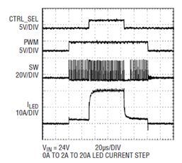
Figure 4: LED current step from 0A ~ 2A to 20A
High efficiency over a wide PWM duty cycle
In portable DLP projectors, power dissipation is an extremely important design parameter. Unlike many parallel high current LED drivers currently on the market, the LT3743 offers exceptional efficiency over a wide PWM duty cycle. By simply delivering power to the load instead of bypassing the power or charging the output capacitor, most of the energy lost in conventional conventional PWM dimming drivers can be saved. Figure 5 shows the efficiency variation over the entire duty cycle when VIN = 12V and a green LED is driven at 0A to 20A.
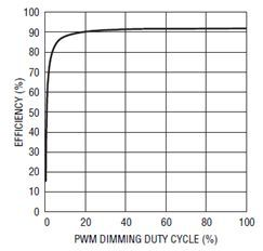
Figure 5: 12V, 20A PWM dimming efficiency (using a green LED)
Downtime and precise activation
When delivering large load currents, the supply undervoltage lockout (UVLO) hysteresis required to perform proper operation is highly dependent on the board layout. For maximum flexibility, the LT3743 has a precision enable threshold and a 5.5μA current source will flow into this pin when the EN/UVLO pin voltage is below 1.55V. Use a voltage divider between the input power and ground to add any hysteresis to the system. To achieve power savings in portable applications, when the EN/UVLO pin voltage is below 0.5V, the LT3743 will be completely disabled and the supply current will be reduced to less than 1μA.
Thermal derating of LED current
When there is any high current load, proper thermal management is extremely important to protect expensive high current LEDs and to avoid damage throughout the system. For high and low control currents, the LT3743 uses the CTRL_T pin to reduce the effective regulated current in the load. When the CTRL_T pin voltage is lower than the control voltage on the CTRL_L or CTRL_H pin, the regulated current will be reduced. The temperature derating is set using a temperature dependent resistor divider connected between the VREF pin and ground.
Output voltage protection
Output voltage protection is important to prevent expensive projector LED damage. The LT3743 uses the FB pin to provide a regulated voltage point for the output. To simplify system design, the LT3743 uses an internal 1V reference to slowly reduce the regulated current when the FB pin voltage reaches 900mV.
Powerful gate driver
To provide sufficient drive capability and reduce switching losses in high current power MOSFETs, the LT3743 uses a very powerful switching MOSFET driver. The on-resistance of the LG and HG PMOS pull-up drivers is typically 2.5Ω. The turn-on resistance of LG and HG NMOS pull-down drivers is typically less than 1.3Ω. In the case where the on-resistance is so low, for applications over 20A, two high-current MOSFETs can be used in parallel. Most LED drivers currently on the market do not provide enough gate drive capability for dimming MOSFETs, so an external gate driver is required. The LT3743 integrates it into PWMGL and PWMGH drivers with a typical 2Ω NMOS pull-down driver and a 3.7Ω PMOS pull-up driver to drive any 5V dimming MOSFET.
Traditional PWM dimming
The LT3743 is adaptable to any traditional PWM dimming method. Parallel output dimming used by competing LED drivers can result in wasted energy and inefficiencies when the LED duty cycle is less than approximately 50%. Since the LT3743 has two levels of current regulation, the regulated current can drop to zero when the shunt is occupied. This provides excellent efficiency even at low LED duty cycles.
Figure 6 shows a 2A LED driver configured with a current-limited parallel output. Note that the CTRL_L pin is tied to ground, the PWMGL pin is used to drive the parallel MOSFET, and the CTRL_SEL pin is used for dimming. With the CTRL_L pin tied to ground, when the CTRL_SEL pin is low, the shunt is taken and the current in the inductor is regulated to 0A. When the CTRL_SEL pin is high, the shunt MOSFET is turned off and the regulated current is determined by the voltage on the CTRL_H pin. Figure 7 shows current-limited parallel PWM dimming with a 12V input.
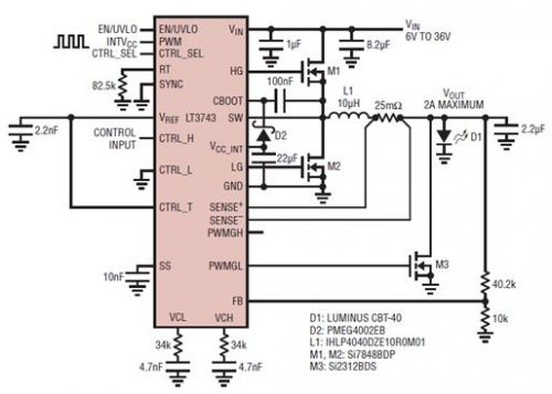
Figure 6: 6V to 36V Input, 2A LED Driver with Current Limited Parallel Output
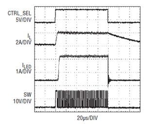
Figure 7: 0A to 2A Current Limited Parallel Output PWM Dimming
In addition to paralleling, the LT3743 can be easily configured to drive a dimming MOSFET in series with the negative side of the LED. This is the preferred PWM dimming method when multiple current states are not required. Figure 8 shows a 6V to 30V, 20A LED driver with diverted negative PWM dimming. Figure 9 shows the conversion negative PWM dimming at 0A to 20A current step and 100:1 dimming ratio.
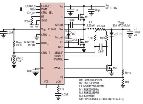
Figure 8: 6V to 30V, 20A LED Driver with Conversion Negative PWM Dimming
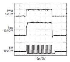
Figure 9: 0A to 20A Conversion Negative PWM Dimming
in conclusion
The LT3743 achieves ultra-fast high current LED rise time and provides accurate current regulation. Thanks to its ability to support multiple current states, it meets the requirements of high-performance cinema-grade DLP projectors by enabling easy mixing of LED colors. In addition to speed, the LT3743's switched-capacitor topology also reduces the board's form factor by allowing the use of a compact low-value inductor. Other features include switching cycle synchronization, overvoltage protection, high efficiency, and the ability to easily adapt to a variety of application needs.
If you want to know more about the products in Detailed explanation of the new dimming scheme based on LT3743 LED driver, please click the product details to view parameters, models, pictures, prices and other information about Constant Current Led Driver,Led Driver 12V,Led Driver 24V,Led Driver 30W.
Whatever you are a group or individual, we will do our best to provide you with accurate and comprehensive message about Detailed explanation of the new dimming scheme based on LT3743 LED driver!
Constant Current Led Driver, Led Driver 12V, Led Driver 24V, Led Driver 30W
Aixuan Lighting & Technology Co., Ltd. http://www.yingjiaoadapters.com